
UHF-band RFID tag sensor for metals
One of the expected applications of an UHF-band RFID tags sensor (for example, AVERY DENNISON Smartrac's Temperature Sensor Dogbone™), which can output sensor code S as an indicator of dielectric constant change by water leakage and temperature in the ambient environment, is the detection of abnormal temperature and water leakage in building and facility maintenance. However, when a conventional RFID tag is attached directly to metal objects, the reflection of electromagnetic waves from the metal surface causes communication problems (For example, Fig. 1 Shape A and Table 1 show zero communication distance).
Following are conventional method to solve the problem: (a) a foam spacer which creates a distance between the RFID tag and the metal surface (b) a magnetic sheet made of soft magnetic material placed between the tag and the metal surface to change the direction of reflection of the incident magnetic flux, (c) the metal itself to which the tag is attached can be (c) the metal itself to which the tag is attached is made into a booster antenna.
Table 1 Relationship between RFID tag configuration and communication distance.

However, in the case of temperature sensing, the RFID tag must be in direct contact with a metal body to measure temperature by heat conduction to the IC section.
We have considered the reason of the significant shortening of the communication distance and the communication failure when RFID tags are attached to a metal body. From the viewpoint of the phase change of electromagnetic waves incident on the metal surface from the air, we assumed that the incident and reflected waves weaken each other due to phase inversion at the fixed end-reflecting surface.
In this case, the angle (θ1 in Fig. 1) between the metal surface and the impedance matching part where the IC chip of the RFID tag is electrically coupled becomes important. We solved the problem of communication failure due to contact of the RFID tag with the metal by optimizing the arrangement and angles of the impedance matching unit with respect to the metal (JP2022-147460, JP2022-143255).

Fig.1 Shape of UHF RFID tag placement on metal plate.
UHF-band RFID tag strain sensor
In the monitoring of vital signs such as body temperature, heart rate, and respiration, there is a need to reduce the burden on the wearer, where the features such as flexibility and light weight of the device for measurement are important issues. To reduce the burden of wearing the device, it should be flexible, lightweight, thin, and a passive sensor that operates with a wireless power supply and does not require batteries or an external power source. A UHF-band RFID tag with sensor functions satisfy these requirements.
We are conducting research and development of a UHF-band RFID tag strain sensor (JP2022-109329). An example of our UHF-band RFID tag strain sensor is illustrated in Fig. 2, in which the basic structure of an RFID tag (IC chip, impedance matching unit, and antenna) and additional radiation conductor are sandwiching flexible gel layers whose thickness can be easily changed by compression. As shown in Fig. 3, the reader RSSI (Received Signal Strength Indicator) value can be wirelessly sensed in response to changes in the thickness D of the gel layer due to strain. In the measurement as shown in Fig. 3, the period of strain change is assumed to be equivalent to the pulse rate per minute of a healthy adult at rest (60 to 100 beats/min).
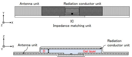
Fig.2 UHF-band RFID tag strain sensor.
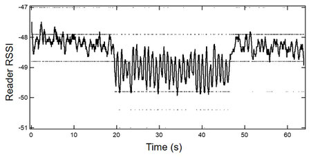
Fig.3 Strain response of UHF-band RFID Tag sensor.
The production of UHF-band RFID tags usually requires large-scale mass-production equipment and a great deal of expense, making it difficult to produce custom products in small lots. We can custom-manufacture and prototype UHF-band RFID tags with various unique characteristics at low cost and in small lots by laser processing (JP2022-109329).